I'm not a big fan of cardioid subwoofer arrays. CSAs have the unpleasant property of producing destructive interference in the sound field, i.e. to the advantage of enabling strongly damped sound emissions behind the loudspeaker assembly, unfortunately, the great disadvantage of purchasing an uneven level distribution with frequency-dependent "side legs" and poorer impulse behaviour in the sound field forwards is added. For these reasons, I refrain from a CSA arrangement whenever possible and first try to reach a compromise with Endfired arrangements. Sometimes, however, external circumstances force us to poorer audio quality, e.g. when emission protection requirements require us not to exceed defined sound pressure levels. This circumstance is due to the already densely populated country and the desired proximity to the place of residence of the guests. However, the prudent sound engineer would be happy to point out to the organiser that “more quiet behind the stage” also means “worse in front of the stage”. For events with local residents in the area, however, often only CSA arrangements help. One more reason to make it as good as possible. In the following, I would like to point out a method that is as simple as it is effective. The manufacturer is obligated to use this method when creating a preset, which of course results in a ‘compulsory set-up’ matching the preset. Despite obvious logic, I haven't met anyone who does this in manual setup on productions that require forced running if either the preset or set-up is not appropriate. One more reason to write it down.
Common practice in CSA measurement
Common practice in CSA measurement
Typically, the following method is used in the CSA measurement:
- Place the measuring microphone behind the subwoofer assembly.
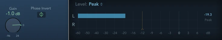
- Play back the measurement signal only via the front loudspeakers and save the measurement as a ‘reference’.
- The delay in the reference channel of the measuring system remains untouched and equal to the first measurement.
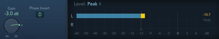
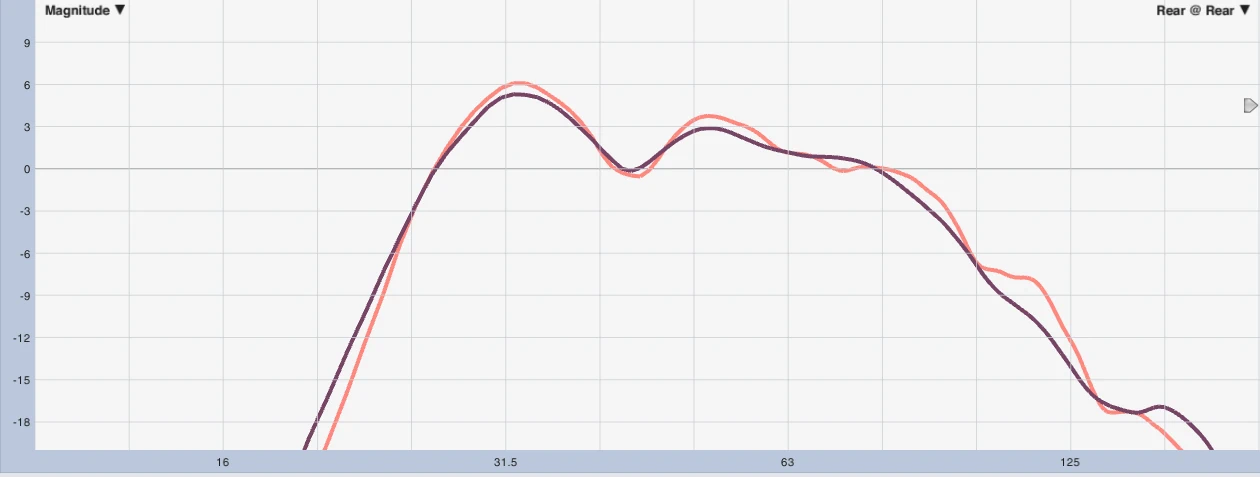
- Now play back the measurement signal only via the rear loudspeaker and add a delay in the input path of the rear loudspeaker until the phase frequency response in the passage of the main energy fits optimally to the signal stored for reference from the front.
- Then invert the polarity of the rear channel.
- Finally, optimally adjust the level of the rear speaker to that of the front signal.
- MANUFACTURED!
Every system technician masters this method during sleep and has probably used it 100 times more often than I do, and you're probably just wondering. “...what does he want from me now?”
The secret to a properly functioning CSA is hidden in point 6. Two 180° phase shifted signals only clear to 100% If the levels are absolutely identical. A level difference of 1dB leads to the resultant level after addition being about 20dB below the input level of a signal. Since the frequency response of the front loudspeaker at the rear position usually does not correspond to that of the frequency response of the rear loudspeaker at the rear position (especially with stacked arrangements), this inevitably leads to level differences over the working range. In addition, especially in indoor applications, reflections and diffuse sound without a suitable phase reference, these can of course not be included in the optimization and rather represent a constant source of interference.
Excursus to the level calculation
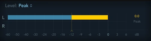
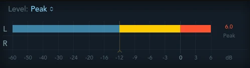
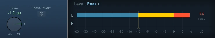

As we can see, when setting up CSA setups, you have to be hellishly careful that the rear levels fit as exactly as possible to the front level located there. Differences of 0-1dB lead to deletions from -∞ to -20dB. If you increase the tolerances to 3dB we only create -10dB attenuation. If the level of the rear subwoofer is -6dB relative to the front, you only reach -6dB attenuation, if you switch off the front sources in this case, nothing changes at the rear level.
But enough of the theory, let's turn now to practice.
Measurements on living objects
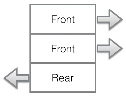
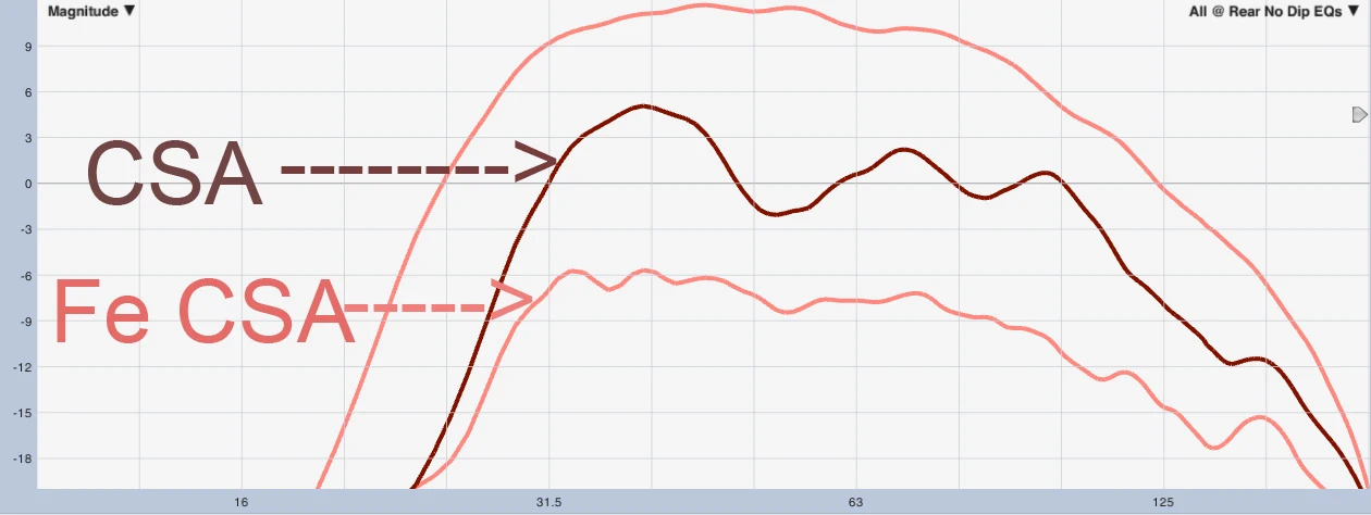
On this example arrangement, the following measurements are based, which were created in the acoustically most unfavorable conditions. ...i.e. basically realistic conditions ⁇
The measurements were averaged to 1/3 octave, the scaling is +12 to -20dB, each box is 3dB.
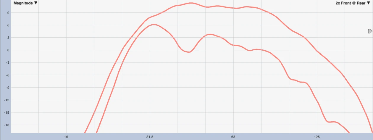
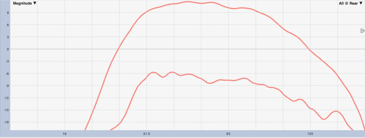
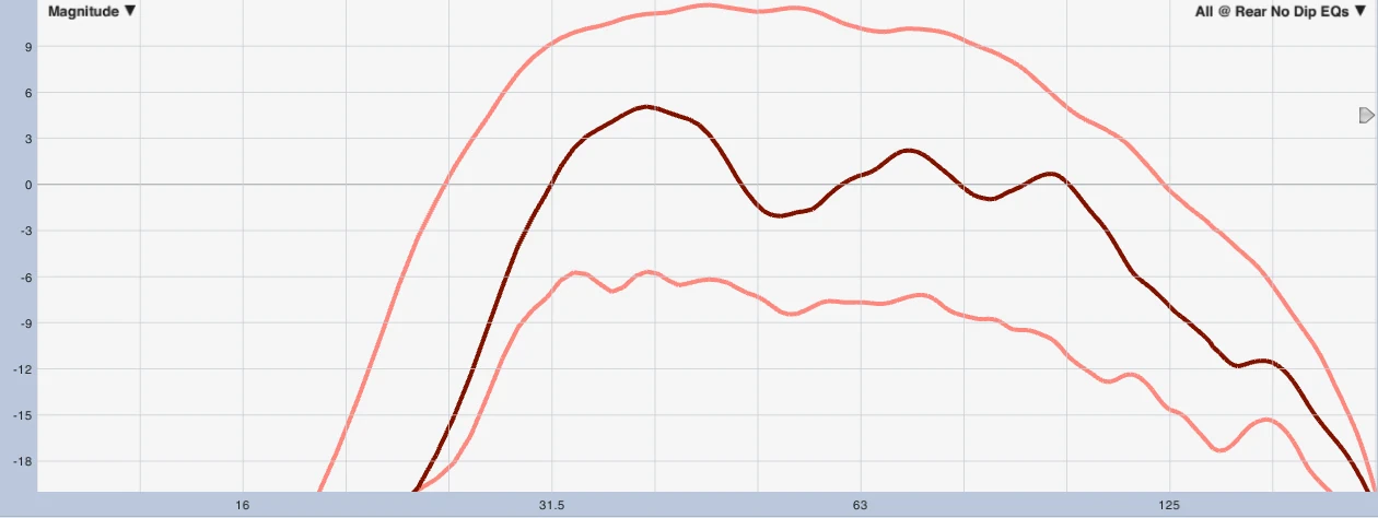
It is a fact that a frequency response equalization of the rear subwoofer in this situation allows for up to 10dB better reverse attenuation. The reason for this is the level difference over the frequency response of the front subwoofer at the rear position, compared to the rear subwoofer at the same position. For example, level differences in the frequency response of 1dB lead to resulting levels of -20dB instead of a complete extinction. Of course, assuming that the phase frequency responses are perfectly shifted by 180°, which is not the case either, and secondly is influenced by the added filters. The effort of setting up is a bit higher, but you will be rewarded with drastically better results.
Basically, I am not telling anything new here and level calculation is also part of the standard repertoire of the sound engineer. However, on the countless productions I have never met anyone who has done this. ...but I haven't met all the system technicians yet ⁇
In order to distinguish the methods used to set up cardioid subwoofer configurations, I propose that this method ’Frequency Enhanced Cardioid Subwoofer Array” [Fe CSA] to name.