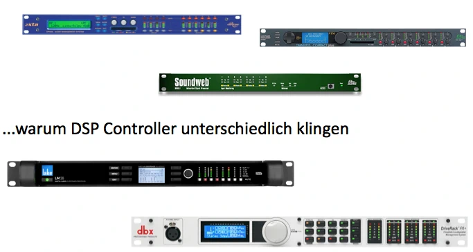
Why do DSP controllers sound different when set up with the same PEQ settings?
If you ask this question to five different Tonleuten you will certainly get ten different answers. Usually, after a quarter of an hour of discussion, you end up in the realm of esoteric mysticism. On the one hand, it is precisely these discussions that make the job so exciting, on the other hand, one cannot simply accept that such a sensitive needle eye as system controllers have extreme tolerances. They are the last link in front of the loudspeaker and its power amplifier and decisively determine the sound and the life of the system. You can argue about the sound and personal preferences of equalizers in mixing console channels and choose them according to the program, but for the selection of system controllers such parameters should not play a role. Their task is clear ... to ensure protection and linear transmission function in the sense of the loudspeaker manufacturer. The fact that the controllers of different manufacturers with the same data provide different results leads to system technicians heroically idolizing individual copies and manufacturers increasingly tend to closed system solutions. The addition of power amplifiers and controllers to the value chain should not play a role for us users at first, after all, the advantages also outweigh the benefits for us if a system sounds the same all over the world.
Who still believes the devices of different manufacturers only sound different because gurus in the R&D departments have secret knowledge about A/D and D/A converters see the following figure.
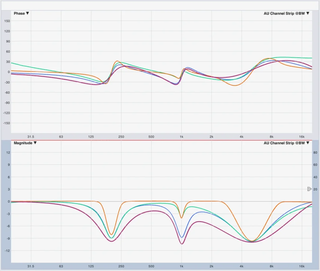
Of course, there are quality differences in processing, converters and computational algorithms. Otherwise, you can not do justice to the fact that the devices in different price ranges are necessary. Of course, these differences also lead to sound differences. However, I do not want to assess or discuss them here. Let's focus on the main factor, which is the definition of bandwidth. As we see in the picture above, this does not seem to be standardized, unlike what we learned in school. Let's take a closer look at the topic.
Definition and conversion of bandwidth
Option 1 (theory)
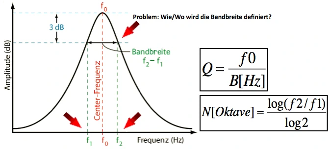
We all know this figure, it tricks us into thinking that the range of parametric equalizers is defined at the -3dB point and can simply be calculated back and forth using the formulas. The advantage is that exam results can be clearly corrected and technicians can use Exel Tools to convert values for Q factors into bandwidth per octave. Unfortunately, this has nothing to do with correct or unambiguous results in practice, otherwise it would hardly lead to results like with the above AU Plug Ins. Absolutely speaking, the whole thing is not a problem either “...just adjust the EQ until it fits”. At the latest when we read the corresponding manufacturer information, the question arises as to why information is displayed at all if it is not interchangeable. Finally, in practice, I would like to transfer the value from device A to device B WITHOUT causing tolerances in the transmission function.
Back to this simple definition at the -3dB point, two questions arise.
1. What about gain values smaller -3dB?
2. What about positive gain values? ...is the behavior of cut and boost necessarily the same?
First of all, let's look at how a parametric EQ is usually constructed.
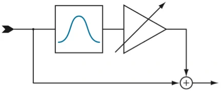
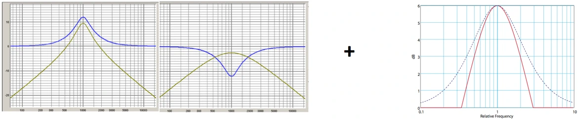
We send the signal through a bandpass 2. Put it in order and mix it with the original. The level of mixing results in the filter gain and for lowering the polarity of the mixed signal is rotated. The result is the following transmission function.
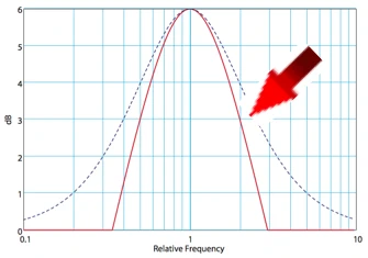
and the resulting PEQ (blue dashed)
If we look at the -3dB point in this figure, we see that the dashed line representing the resulting parametric EQ is wider than that of the bandpass itself. This is due to the fact that the slope of the bandpass or its order is not infinitely high. What we can remember, however, is that the bandwidth of a bandpass is always defined at the -3dB point. Surely every communications technician will see it the same way. Unfortunately, this definition does not necessarily apply to all parametric EQs, a construct that sound engineers have created for themselves.
Here are the first two possible definitions.
Definition ⁇ Option 1 (bandpass bandwidth uncompensated / bandpass Q)
1. The bandwidth of the underlying bandpass is simply taken as a definition of the bandwidth of the PEQ. The fact that the resulting bandwidth is necessarily wider is ignored.
Definition ⁇ Option 2 (bandpass bandwidth fixed compensated)
2. In addition, a fixed offset for error compensation is defined, which then approximates to a gain value of the PEQ.
Now we know two possibilities, one generally inaccurate and one relatively inaccurate as soon as one deviates from the gain value on the basis of which one has defined the offset. In addition, we have completely ignored the -3dB problem of the bandpass so far. This leads us now to the next two definition possibilities, which have the aim to take smaller gain values better into account ...it would not be expedient to minimize the tolerances only at +/-10dB gain values.
Possibility of definition 3 + 4
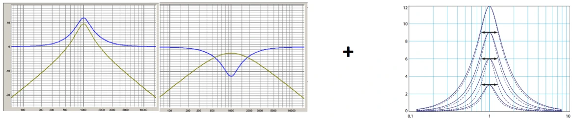
First, it is defined that the bandwidth is not defined at the -3dB point but at the 3dB of the peak point.
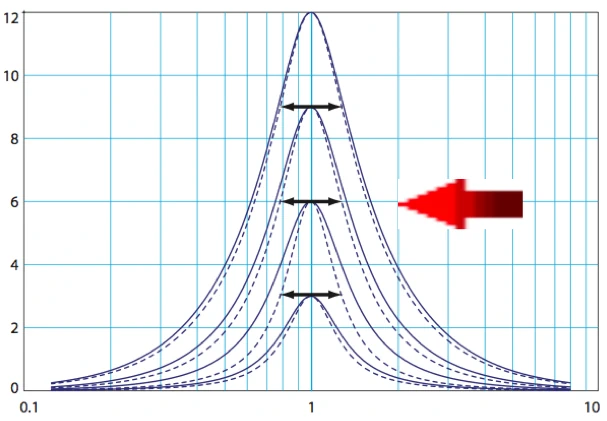
Definition ⁇ Possibility 3 (3dB hybrid method ...dotted line)
For gain values less than 6dB, the bandwidth is defined using half of the filter gain. For gain values greater than 6dB, the “normal” definition at the bandpass is used.
Definition ⁇ Possibility 4 (db/2 method)
This method basically defines the bandwidth as if the filter gain was only half, resulting in narrower filters at higher gains.
Now we know four ways to define the bandwidth of a parametric equalizer. They all build on the bandwidth of the underlying bandpass and more or less compensate for the resulting tolerances. But what about the cut/boost behavior? Are parametric filters based on “mixed” tape passes always the same? Does it matter if we raise or lower?
Cut vs. Boost
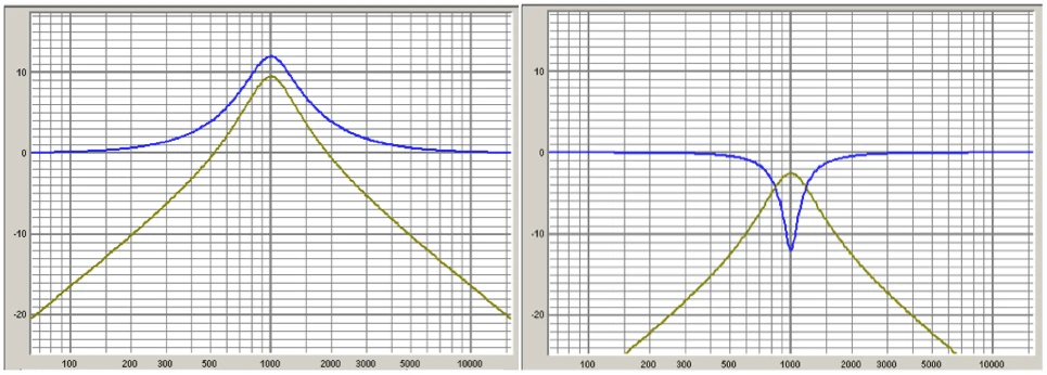
As we know, a cut behavior is generated by inversion or polarity reversal of the mixed bandpass signal. As a matter of course one assumes that the bandwidth remains the same if one leaves the fingers of the Q and rotates from -5 to +5dB gain. ...except for a few...mostly expensive exceptions, that's the way it is. Considering that the bandwidth of the bandpass is defined at the -3dB point and there is no +3dB point at the bandpass, we should expect that cut filters are naturally narrower than boost filters. This is exactly what happens if you do not compensate for the cut/boost behavior.
Definition ⁇ Possibility 5 (asymmetric filters / Constant Q filter*)
The bandwidth/Q factor is constantly defined regardless of cut or boost. The underlying bandpass has the same bandwidth or quality regardless of cut or boost.
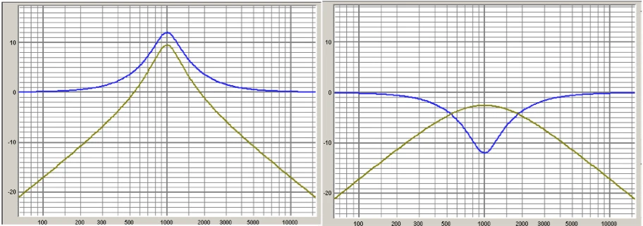
Definition ⁇ Possibility 6 (symmetric filter / variable Q* / reciprocalpeak-dip)
The cut/boost behavior is symetrized by adjusting the bandpass bandwidth. ...two identical filters, a cut of a boost, cancel each other out phase-linearly.
Use of the terms Constant Q* & Variable Q*
OK, so there are two more ways to combine them with the first four methods. Symmetric or asymmetric cut/boost behavior. However, the use of names can also lead to confusion. For the designer, perhaps the resulting asymmetric behavior is a ‘constant Q’ filter because the bandpass has a constant bandwidth. Perhaps the marketing department thinks the other way around and says ‘constantly Q’ refers to cut/boost control behaviour. Other manufacturers may say ‘variable Q’ is called db/2 method and leads to narrower filters at higher gains. Still other manufacturers do it a bit differently and call their filters ‘adaptive Q’ In the end, you have to question the manufacturer’s name, which, however, presupposes that it also describes it. I simply reduce the possibilities for the designation to the two obvious ones:
Option 1 (developer view)
Referring to the technical procedure -> Contstant Q = asym. filters
Option 2 (User view)
Referring to the result-> Contstant Q = sym. filters
Who does what?
Unfortunately, manufacturers rarely document your definition of bandwidth. In practice, however, the methods described above have proven themselves, they are the basis for what we find on the market. It is therefore relatively easy to find out from a measurement point of view which method the manufacturer uses. For some products, you can also switch the method/definition, such as the BSS Soundweb. During the research on this article, I came across the following results.
XTA ⁇ TOA ⁇ Ashley ⁇ Rane ⁇ EAW
Symmetric cut/boost behavior + definition of bandwidth at -3dB from the bandpass point by varying the Q factor of the underlying bandpass.
BSS (Omdidrive, Soundweb) ⁇ Mediamatrix
Symmetric cut/boost behavior + definition of bandwidth at -3dB from peak point by variation of the Q factor using the 3dB hybrid method
Conversion and transfer of manufacturer information
Manufacturers of "open" systems publish processor settings for their loudspeaker systems. In the best case, they specify the manufacturer/type of processors for which the settings fit. The user is now responsible for converting/converting this information for other processors using various Exel tools. If the manufacturer has not documented his original claim, we already have the first source of error here. The second source of error then lies with the user, who is responsible for choosing the correct conversion. In the worst case, the mistakes accumulate here.
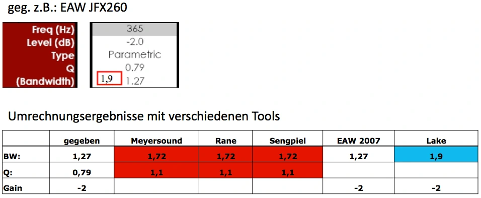
Practical example
As a colleague always says so nicely “...you can do it that way, but then it's just shit”. Now let's look at what happens in practice if we stick to the above example of the EAW JFX260 and combine it with an EAW LA400 subwoofer. Without the knowledge of how to theoretically correctly convert and apply Q/BW data, various results can be generated. The system processor in this example is a Lake LM44, which requires special attention due to the calculation method used, Raised Cosine Equalisation. The manufacturer EAW provides data for Q and bandwidth in its Processor Settings Spec Sheets without documenting the definition method. In the EAW Exeltool (see download link above) it provides the missing information in the 2007 version. EAW specifies the Q factor and bandwidth for bandpass Q definition in the ProzSettings Sheets and allows conversion for BSS and media matrix using the 3dB hybrid method. The first source of error for the user of Lake Processing is now the assumption that he can use the bandwidth information from the Spec Sheet directly. That's wrong! The Q value must be converted specifically for Lake Processing, which in this example results in a bandwidth of 1.9 instead of 1.27 for an exemplary PEQ.
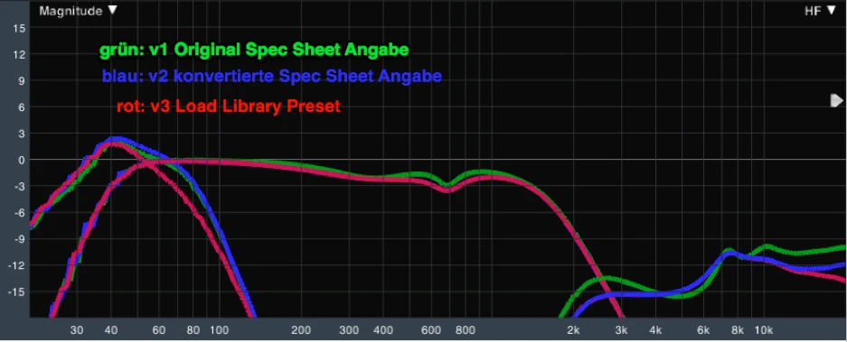
The green curve shows the transmission function based on the original EAW ProzSettings Sheet, e.g. BW 1.27 instead of 1.9. These values have to be converted for Lake Processing with Raised Cosine Equalisation, which represents the blue curve. in the MF band it is identical to the red curve which represents the setting from the Lake Load Library, which by the way was made by the manufacturer himself. We therefore generate here by incorrect application e.g. differences of + 4dB in 2-3kHz ... with an EAW speaker which is known to be very "flat" tuned in this range.
Here, of course, the question now arises: does EAW want the Lake Load Library Preset to have 2-3dB less RF? One should think that a Lake Loadlibrary preset that comes from the manufacturer operates the loudspeaker in the best possible way according to its philosophy, which raises the question of the ‘real’ reference. So let's take a look at the Lake Loadlibrary preset again against the EAW UX8800 system processor, which in contrast to the Lake FIR contains filtered focused presets.
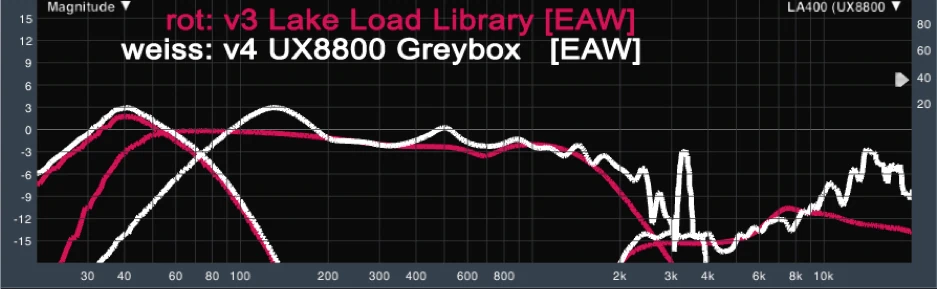
Here you can now see and hear such extreme differences that you have to ask yourself whether EAW pursues a new philosophy with the Focused Greyboxes presets or it is simply a marketing gag for Focused Greyboxes. It is undisputed that the Focussed Technology developed by David Gunness for EAW works excellently in an NT56, for example. The speaker has an absolutely linear transmission function and sounds just as excellent as it looks metrologically. The same applies to a non-focused powered JFX260 which is absolutely flat tuned whether fullrange passive or BI amped operated. From the series dances the Focused Greybox, which subjectively somehow has more mids and heights and has got a small LF bump to compensate for the deafness. The UX8800 Greybox Setting is FIR focused, which of course is not the Lake Loadlibrary Preset, so differences in the transmission function are of course to be expected, but the tonal tuning should follow the manufacturer's philosophy and not sound seriously different. Now, of course, you can say that everything that is not focused is old MX presets and no longer a reference, the real reference can only be the current Greybox setting. In this case, I just see it differently, I like the linear tuning of EAW presets and loudspeakers ...the speaker should give out what I put in and I am responsible for the sound. By the way, the EAW focused Greyboxsetting can be loaded directly into a PLM power amplifier or a Powersoft DSP power amplifier. Without assessing this, however, the question arises: What is the “right” reference?
conclusion
1. The definition of bandwidth for parametric filters is not standardized.
2. Manufacturers define bandwidth differently.
3. Manufacturers do not sufficiently document this definition. (Exceptions confirm the rule.
4. In practice, a few definitions/methods are used.
5. The user must observe this circumstance when converting Q & BW data.
6. There is no universal tool for conversion that always delivers the right results.
7. On the manufacturer's side, the trend is towards closed system solutions where the processing comes from our own company, or a few third-party manufacturers are specified.
8. Conversion results are inaccurate.
left
Of course, I didn't come up with all this myself and pulled it by the hair, although the research on this topic was like browsing in chaos. If I write that the manufacturers do not document carefully enough how they define the bandwidth, then of course I take those who do this excellently and document in white papers or the like. Attached links to the main sources:
Libary
White papers
tools
JAES JAES Volume 45 Issue 1/2 pp. 37-62; February 1997